
Time-Gated Raman Spectroscopy Principles and Applications of Pulsed Microchip Lasers
1. Raman Scattering
In 1928, Indian physicist C. V. Raman discovered the Raman scattering effect. In his experiments, when monochromatic light (usually laser light) irradiates a substance, photons undergo elastic collisions with molecules. The resulting scattered light shares the same wavelength as incident light and carries no useful information; this phenomenon is known as Rayleigh scattering. When photons collide inelastically with molecules, the wavelength of scattered light shifts relative to that of incident light — this is defined as Raman scattering[1].
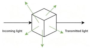
【Figure 1: Schematic diagram of light scattering】
Raman spectra act as unique chemical fingerprints for specific molecules or materials, enabling rapid material identification and differentiation. Databases of Raman spectra contain thousands of spectral entries, and target substances can be quickly identified by spectral matching.
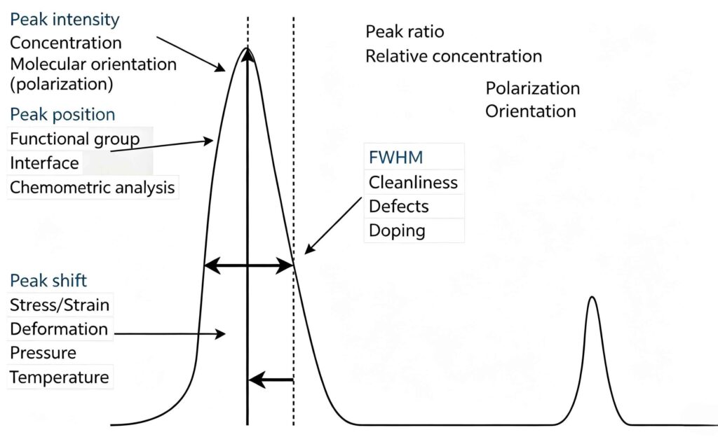
【Figure 2: Schematic diagram of Raman spectral peak-parameter analysis】
When laser light illuminates a sample, Raman scattering is induced alongside fluorescence. Raman scattering is extremely weak, whereas fluorescence intensity is 106-108 times higher. Consequently, fluorescence severely compromises the accuracy of Raman detection[2].
2. Time-Gated Raman Spectroscopy
Following the widespread adoption of Raman spectroscopy, remote Raman spectroscopy emerged in the 1990s. The earliest remote Raman technique was reported in 1992: Angel et al. employed a visible-light remote Raman spectrometer with an Ar⁺ ion laser to detect multiple salts including solid and liquid sodium nitrate at a distance of 17 m[3].
Key technologies for remote Raman spectroscopy include time-gating, laser-wavelength selection, signal-collection systems, and optical-path design and optimization.
Molecules possess small Raman scattering cross-sections, so Raman signals are susceptible to environmental light and fluorescence interference. Remote Raman signals decay with increasing detection distance. Ambient solar light further degrades signal strength, undermining the sensitivity and accuracy of remote Raman measurements.
Continuous-wave lasers cannot adequately suppress background fluorescence in remote Raman detection. By contrast, time-gating technology suppresses solar-light interference and back-scattering noise[4]. Combining pulsed lasers with time-gating greatly improves the signal-to-noise ratio (SNR) of remote Raman spectra.
Although fluorescence out-intensifies Raman signals, the two processes differ drastically in lifetime: Raman scattering lasts on the picosecond timescale, while fluorescence persists for nanoseconds. Time-gating exploits this temporal difference by synchronizing pulsed excitation and signal acquisition to extract Raman signals and reject fluorescence. After a pulsed laser excites the sample, a programmed delay is applied. The delay equals half the photon flight time corresponding to the detection distance. When Raman photons arrive at the gated camera, the gate opens with a gate width comparable to the laser pulse width. The gate then closes to block most fluorescence interference, substantially suppressing background fluorescence and boosting SNR.
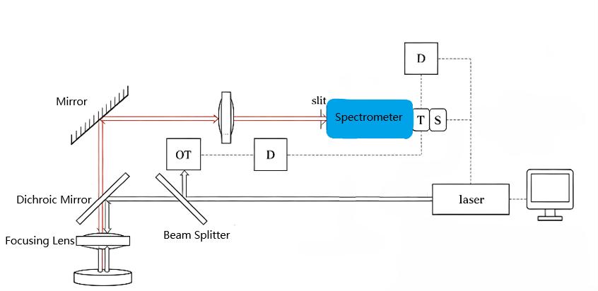
【Figure 3: Schematic diagram of time-gated Raman system】
A well-calibrated time-gating system maximizes collected Raman photons while minimizing background inputs such as fluorescence. Gate delay and gate width depend on detection range and laser pulse width, and must be adjusted for different operating conditions.
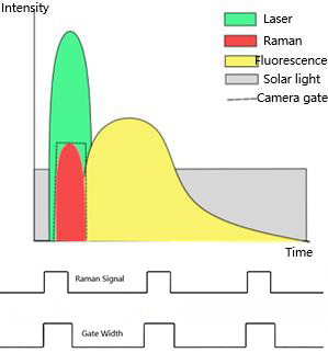
【Figure 4: Schematic diagram of time-gating principle】
3. Effects of Different Laser Wavelengths
Laser wavelengths span ultraviolet, visible, and infrared bands. Raman scattering intensity is proportional to the inverse fourth power of excitation wavelength (I∝1/λ4) [5]. Most remote-Raman systems adopt visible-band lasers, especially the 532 nm frequency-doubled Nd:YAG solid-state laser, for its maturity and stable performance suitable for most applications.
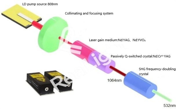
【Figure 5: Schematic diagram of Reallight microchip laser】
In time-gated Raman measurements, ultraviolet excitation avoids most visible-range fluorescence backgrounds and enhances resolution for weak characteristic signals. It is therefore widely deployed for stand-off detection of hazardous chemicals, explosives, and field minerals. Two mainstream ultraviolet sources are used in research and engineering: 355 nm near-ultraviolet light (third harmonic of Nd:YAG) and 266 nm deep-ultraviolet light (fourth harmonic of Nd:YAG). These two wavelengths differ in Raman-signal strength, fluorescence suppression, atmospheric transmission, optical compatibility, and operating-condition adaptability, which directly determine detection range, SNR, and identification accuracy of remote-Raman systems.
Per Raman-scattering physics, shorter-wavelength excitation yields stronger scattering. Under identical pump power, theoretical calculations predict that 266 nm excitation generates approximately 3.16-fold higher Raman intensity than 355 nm excitation. Moreover, 266 nm can trigger ultraviolet pre-resonance Raman effects for aromatic organics and energetic materials, further amplifying weak analyte responses and improving trace-level detection sensitivity.
Fluorescence-suppression performance of the 266 nm deep-ultraviolet source stands out. Spontaneous fluorescence from most organics and explosives lies above 280 nm. Under 266 nm excitation, generated Raman signals fall within the deep-ultraviolet band, spectrally separated from fluorescence. This intrinsically lowers fluorescence baseline noise and prevents fluorescence from masking weak Raman peaks. When excited at 355 nm near-ultraviolet, most organics produce broad-band fluorescence that tends to obscure faint Raman features; hence 355 nm is better suited for inorganic minerals and low-fluorescence industrial media.
For outdoor long-range detection under atmospheric conditions, 355 nm provides greater practical value. The 266 nm deep-ultraviolet band suffers strong absorption and scattering by atmospheric oxygen, ozone, and aerosols, limiting open-air effective detection distance typically below 20 m. By contrast, 355 nm falls within an ultraviolet atmospheric transmission window with low propagation loss, supporting 20-40 m medium-range detection for field inspection and open-site industrial operations.
266 nm deep-ultraviolet laser cannot transmit through ordinary optical glass, so optical components must be fabricated from special materials such as calcium fluoride and high-purity fused silica. Optical coatings degrade under prolonged ultraviolet irradiation, and detectors require ultraviolet-enhanced ICCD or EMCCD devices. As a result, 266 nm systems incur high costs and present assembly-and-alignment challenges. Conversely, 355 nm optical technology is mature; standard fused-silica optics suffice, coatings exhibit high stability, and component options are abundant. 355 nm lasers support high-repetition-rate and high-average-power output, delivering high system reliability and low maintenance overhead.
Regarding sample safety and measurement stability: higher-energy 266 nm photons may induce photochemical reactions and surface ablation when irradiating photosensitive energetic materials. 355 nm has milder photochemical activity, causing less perturbation or damage to samples and delivering more stable measurements.
In summary:The 266 nm laser fits short-range, high-fluorescence-background scenarios requiring high-precision identification of trace organics and explosives.The 355 nm laser is preferred for medium-range open-air engineering-oriented remote Raman detection, primarily targeting inorganic analytes.
4. Application of Reallight MCC-Series Pulsed Microchip Lasers in Time-Gated Remote-Raman Systems
Beyond wavelength selection, noise suppression in time-gated remote-Raman systems critically relies on precise timing synchronization between the laser and gated detector. The system records the exact moment of laser-pulse emission to calculate photon-flight delays and control ICCD gate intervals. This synchronization is usually implemented using a photodiode (PD).
The PD serves as a timing sensor, converting incoming laser pulses into electrical trigger signals. Using PD-detected pulse timing as a reference baseline, the system calculates round-trip photon flight time according to detection distance and sets corresponding delay and gate width. This ensures that the detector gate opens exactly when Raman-scattered photons arrive, rejecting delayed fluorescence and stray ambient light. Timing-synchronization accuracy sets the upper bound of achievable SNR; large trigger jitter causes loss of valid Raman signal or admission of excessive background noise.
Meeting stringent timing and performance demands of time-gated remote-Raman detection, the Reallight MCC-series microchip lasers cover three mainstream excitation bands: 532 nm, 355 nm, and 266 nm. Adopting monolithic microchip resonator architecture, this series delivers narrow pulse output, excellent energy stability, low timing jitter, and high-repetition-rate continuous operation. All MCC-series lasers support PD integration for synchronized data-acquisition setups, complying with pulsed excitation and time-delayed gated acquisition workflows for time-gated Raman, and offering wavelength options for diverse measurement scenarios.
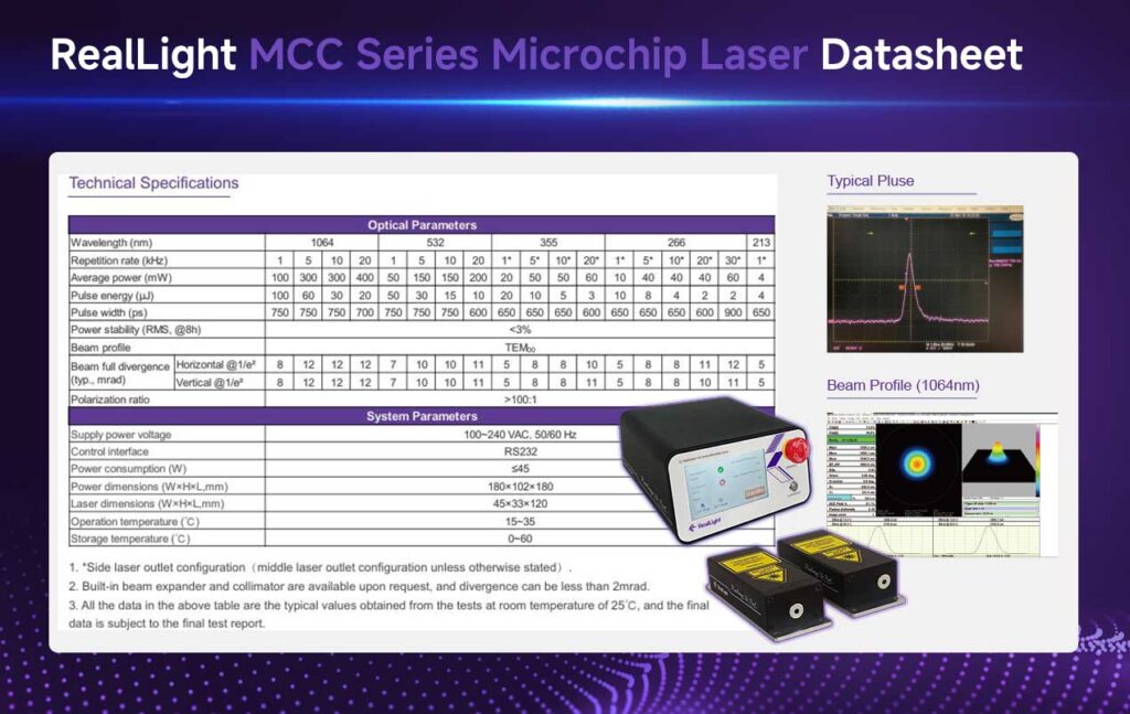
【Figure 6: Specification table of Reallight MCC-series microchip lasers】
· MCC-532 nm: Mature, cost-effective, and with good atmospheric transmission, suitable for general-purpose time-gated remote-Raman platforms. System performance is dominated by timing alignment between PD and gated cameras. Noise reduction is realized in time domain. Typical applications include low-fluorescence inorganic-mineral detection and optical-path/timing-algorithm validation test-beds.
· MCC-355 nm near-ultraviolet: Optimized for field-deployed engineering instruments. Compared with 532 nm, it provides intrinsic partial fluorescence suppression, further augmented by PD-based time-gating for dual-mode background rejection. It uses readily available optical components without extensive special ultraviolet optics, ensuring high equipment robustness. Use-cases include open-plant hazardous-chemical inspection and long-range field mineral screening.
· MCC-266 nm deep-ultraviolet: Advantageous for short-range trace-organic and explosive detection under heavy-fluorescence interference. Raman signals generated by 266 nm excitation are spectrally separated from organic fluorescence, and pre-resonance Raman enhancement improves trace-analyte response. Coupled with PD-enabled precise timing, time-gating removes residual stray light for high-sensitivity detection. Target scenarios include port security screening and trace hazardous-chemical identification in confined spaces.
Disclaimer: Part of the content in this document is sourced from the internet. It is intended solely for technical research and academic exchange. If factual or academic inaccuracies are noted, feedback is welcome. Should any copyright concerns arise, please contact us for prompt verification and removal.
참고 자료
[1] Raman C V. A new radiation[J]. Indian Journal of Physics, 1928, 2: 387-398.
[2] Liu Yingli, Mu Taotao, Chen Shaohua. Research progress of shift-excitation difference Raman spectroscopy[J]. Laser & Optoelectronics Progress, 2024, 61(9): 0900003. DOI:10.3788/LOP231206
[3] Shreve A P, Cherepy N J, Mathies R A. Effective rejection of fluorescence interference in Raman spectroscopy using a shifted excitation difference technique[J]. Applied Spectroscopy, 1992, 46(4):707-711.
[4] Fang Zhengjun, Zhang Shiwei, Jin Pengcheng, et al. Remote Raman detection based on gated single-photon camera[J]. Journal of Light Scattering, 2020, 32(2): 166-170.
[5] Wang Yanding, Liu Xiaomeng. Research progress of remote Raman spectroscopy[J]. Chinese Journal of Quantum Electronics, 2019, 36(3): 257-263.
자주 묻는 질문
1. Why is time-gating technology required for remote Raman spectroscopy?
Time-gating is one of the technical approaches for remote Raman spectroscopy. By adjusting the delay and gate width of the gating system, Raman signals are selected to enter the spectrometer while other background signals are blocked. As a result, the signal-to-noise ratio (SNR) of Raman signals acquired by the spectrometer is improved.
2. How does PD trigger synchronization improve the signal-to-noise ratio for pulsed lasers in time-gated Raman systems?
Once the photodiode (PD) detects laser output, it generates an electrical signal to start the timing system. Combined with the detection distance, the round-trip flight time of photons is calculated. The gate opens exactly when Raman photons arrive and closes after all Raman signals have been received. Consequently, the majority of signals entering the spectrometer are Raman signals with very little noise, which raises the signal-to-noise ratio.





 777
777